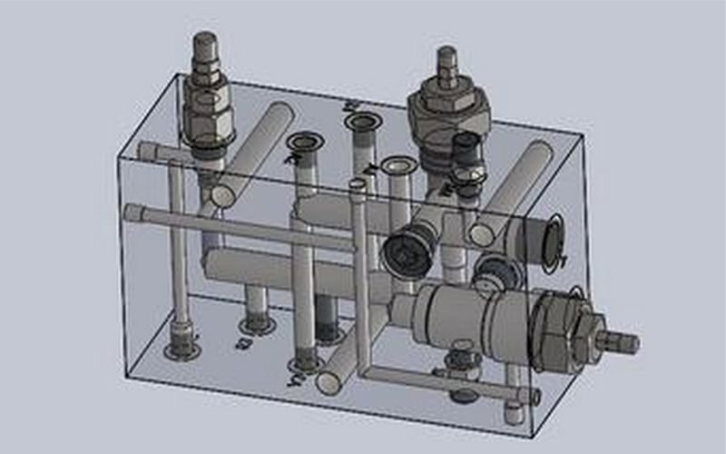
Hydraulic components model of production: in order to realize hydraulic valve on the manifold blocks around the reasonable decorate and arrange the correct oil hole (the hole will be connected to the common oil way hole), can according to the outline dimension of the hydraulic valve and oil mouth location model, the production of hydraulic components in advance on the relevant views of manifold blocks, arrange appropriate location. For the simple circuit is not required to make hydraulic components sample, direct layout can be.
The diameter of the hole and the thickness of the wall between the oil hole can be determined. The class is through the oil hole, including through the upper and lower stacked surface of the public hole, the installation of hydraulic valve on the three sides of the direct valve and the oil port of the valve, the other side of the installation of the pipe joint hole, not directly with the valve oil port of the middle hole is the process hole four; The second type is the connection hole, which includes the fixed hydraulic valve positioning pin hole and screw hole (screw hole), into a pile of bolt hole (light hole) to connect each integrated block; The third type is the lifting screw hole of more than 30kg integrated block.
1. Determine the diameter of oil passage
(1) the diameter of the hole connected with the oil port of the valve shall be the same as the diameter of the oil port of the hydraulic valve.
(2) the diameter of the hole connected with the pipe joint shall generally be according to the flow through and the allowable flow rate, but the hole hole shall be drilled and tapped according to the pipe joint thread path.
(3) screw plug or ball expansion plug should be used to plug the process hole.
2. The diameter of the pressure oil hole and return oil hole in the common channel can be determined by analogy with the diameter of the hole in the series of integrated blocks with the same pressure level. The diameter of the oil drain hole is generally determined by experience.
(1) determination of connection hole diameter
(2) the diameter of the locating pin hole of the fixed hydraulic valve and the diameter of the screw hole (screw hole) shall be the same as the diameter of the locating pin of the selected hydraulic valve and the screw diameter of the screw hole for the matching requirements. The specification of the bolts connecting the assembly can be determined by analogy with the connection bolts of a series of assembly blocks of the same pressure class, and can also be obtained by strength calculation.


 Page location :

