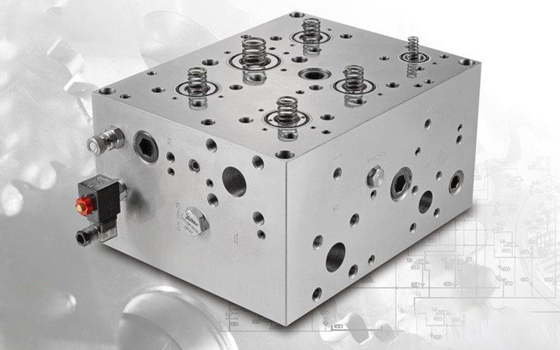
Hydraulic system for the appearance of beauty, volume reduction, easy to control, etc., the action of the valve is highly concentrated together, so the design of the integrated block became our problem. How can we design to meet our needs? This time we will talk about the design and production process of the integrated block;
1. Before designing the valve block, draw the detailed schematic diagram of the integrated block (the schematic diagram of the integrated block is drawn according to the hydraulic system principle), and indicate each functional interface (e.g., P.A.B.T.X). Determine the direction of oil inlet, oil outlet and execution interface.
2. The main material of the integrated block is 35# forged steel or continuous casting. Of course, aluminum or stainless steel materials will be used in special places.
3. Generally, when designing the main oil hole of the integrated block, it is necessary to consider whether the processing is convenient and the loss of flow assistant.
4. The large side length of the integration block shall not exceed 600mm, and the number of two-way plug-in valves shall not exceed 8.
5. The design should consider to improve the deep hole technology, considering the length of the bit, can use the butt hole at both ends. Drill both ends to ensure the verticality of the hole to avoid hole deviation.
6. Enough wall thickness should be left between each hole. When the material is steel, the wall thickness of oil hole and oil hole and pressure oil hole must be more than 5mm, and the wall thickness of oil return hole and high pressure hole must be more than 4mm. The wall thickness of the low pressure hole and the low pressure hole may be 3 mm. Ball mill cast iron: high pressure oil hole and high pressure oil hole at least 8 mm above. The wall thickness of high pressure oil hole and return oil hole is more than 6 mm, and that of low pressure oil hole and return oil hole is more than 4 mm. The following formula:
The delta = pd / 2 (sigma)
[sigma] = sigma b/n
Where, p --Large working pressure,MPa;
[sigma]-- allowable stress of material,MPa;
B -- tensile strength of material,MPa;
N -- safety factor.
7. Therefore, the burrs in each oil hole, especially at the intersection between the hole and the hole, should be carefully removed. Check the oil hole with the probe lamp to see if it is consistent with the drawing. Chamfer C1.5x1.5 at each corner of the block.
8. The bonding surface with hydraulic valve or flange shall be processed by plane grinding, and the surface roughness shall reach Ra greater than or equal to 0.4um. Make sure the planes are perpendicular. After finishing, each surface shall not be crushed, scratch and other defects. Each oil hole shall be stamped according to the corresponding drawing (mark the oil hole function, such as: P,T,A,B,X,Y,G, etc.).
9. After processing, the integrated block shall be repeatedly washed with anti-rust cleaning fluid and high-pressure gun. If the integrated block is not cleaned for the time being, each oil hole shall be sealed with American paper to avoid falling into the dirty oil inlet hole.
10. The circuit board is finished and the next step is to assemble it.


 Page location :

