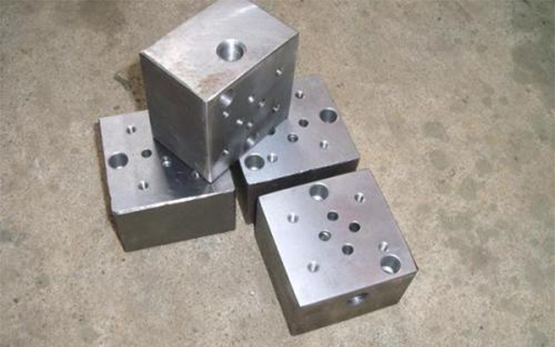
Superposition hydraulic valve, referred to as superposition valve, is a new type of hydraulic element developed on the basis of integrated plate-type valve in recent ten years. This kind of valve not only has the working function of plate-type hydraulic valve, its valve body itself also has the function of channel body at the same time, thus can use its upper and lower mounting surface to show superposition type tubless connection, constitute the integrated hydraulic system.
Stack valve self - contained system. The size, position and number of the main oil channel and screw holes of each size series superposition valve are the same as the plate reversing valve of the corresponding size. Therefore, the stack valves of the same one pass series can be combined and stacked to form different systems as required.
The following dalan hydraulic manufacturers to introduce the design of the hydraulic integrated block:
1) the material of the block structure is generally cast iron or forged steel. The low-pressure fixed equipment can be made of cast iron. The blocks are processed into cubes or cuboids. Generally, in addition to one side of the installation of the hydraulic actuator (hydraulic cylinder or hydraulic motor) pipe joints, the other three sides of the installation of standard plate hydraulic valves and a small number of stacked valves or cartridge valves, the oil between these valves by the oil block internal channel hole to achieve, the upper and lower two sides of the block for the overlap between the joint surface.
A simpler hydraulic system with fewer valves can be installed on the same integrated block. If the hydraulic system is complex, more control valves, it is necessary to take the form of multiple integration block stack.
If the system is a more complex hydraulic system, various valves can be installed on the overlapping integrated blocks, the top and bottom are generally the overlapping joint surface, drilled with the common pressure oil hole P, public return oil hole T, oil leakage hole L and 4 bolt holes for stacking fastening.
P hole, the hydraulic pump output pressure oil after pressure adjustment into the public pressure oil hole P, as the supply of the unit loop pressure oil public oil source.
T hole, the oil return of each unit loop goes to the common oil return hole T and flows back to the tank.
L hole, each hydraulic valve oil leakage, unified through the public oil leakage hole flow back to the tank.
2) determine the dimensions of the integrated block structure and meet the requirements of valve installation, hole arrangement and other technological requirements. In order to reduce the process hole, shorten the length of the hole, the installation position of the valve after careful consideration, so that the connection oil hole as far as possible in the same vertical surface, must ensure that the coordinates of the three public oil hole is the same, so that the stack up to form three main channels.
The inner diameter of each oil hole should meet the requirements of allowable flow rate. The pore diameter should be determined by referring to the diameter of the pipe. The pore diameter directly connected with the valve should be equal to the oil hole diameter of the installed valve.
Hydraulic integrated block design should pay attention to several aspects:
A. selection and installation size of valve;
B. For the structure of the whole machine and the layout of pipelines, the position of the pipe on the valve plate should be selected according to the principle of beautiful appearance, fewer pipe bends and smooth pipeline;
C. specific design of valve body entering at two points according to a and b;
D. During the design, attention should be paid to the choice of the wall thickness of the pressure hole. The actual situation depends on the pressure and the valve plate material;
E. In addition, pay attention to the technical requirements when drilling the valve plate, such as the deflection error of the slender hole bit;
F. Installation surface roughness requirements of disc valves and burr removal of intersecting holes;
G, joint hole spacing requirements to prevent interference between the two joints and other phenomena are the valve design should pay attention to.
For medium and low pressure systems, the wall thickness between oil holes is 6mm, not less than 5mm, and the high pressure system should be larger.


 Page location :

